Jockying for position & Gauging success.

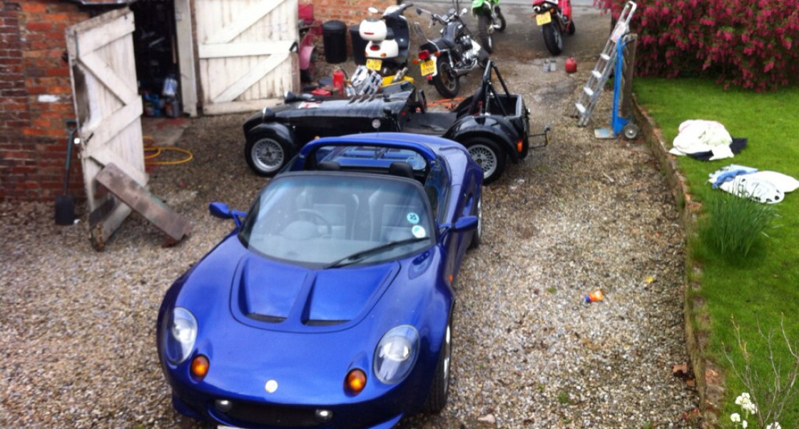
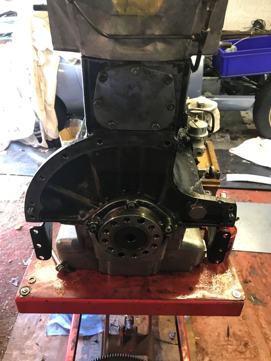
When The engine came out for its rebuild I noticed a peculiar problem with the fan belt. It couldn’t come off. Well it could if I cut it, but then a new one wouldn’t go on, perhaps an even bigger problem.

IMG_5357

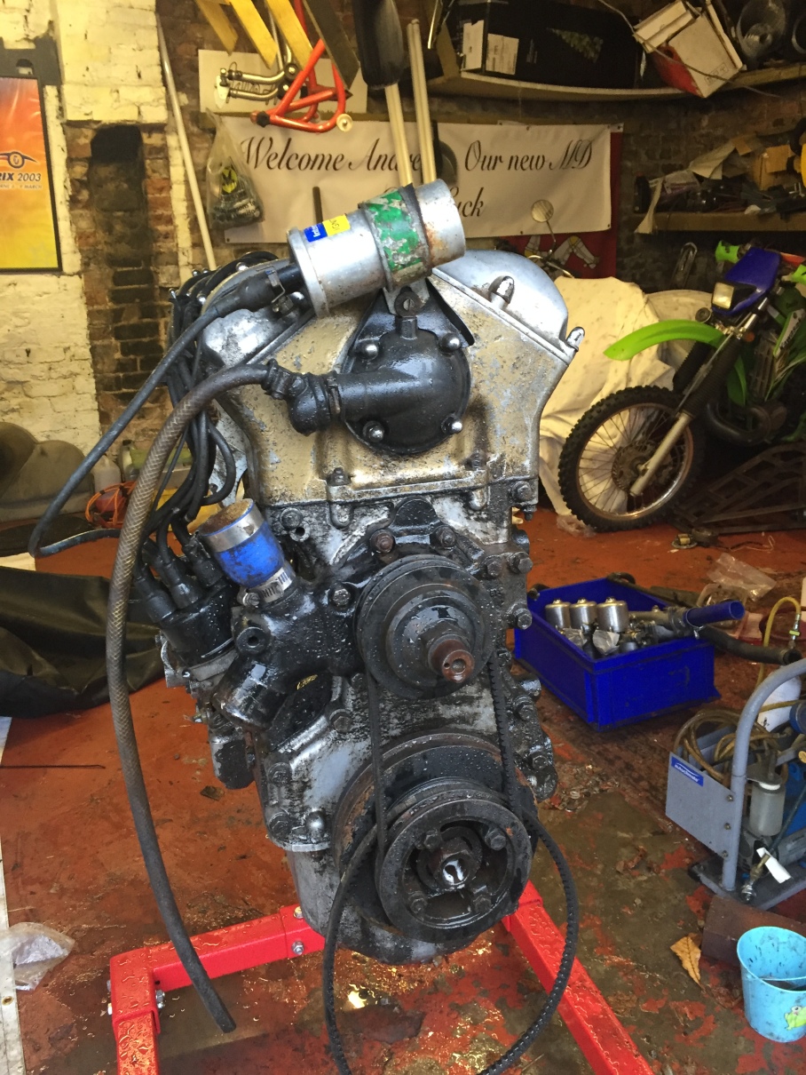
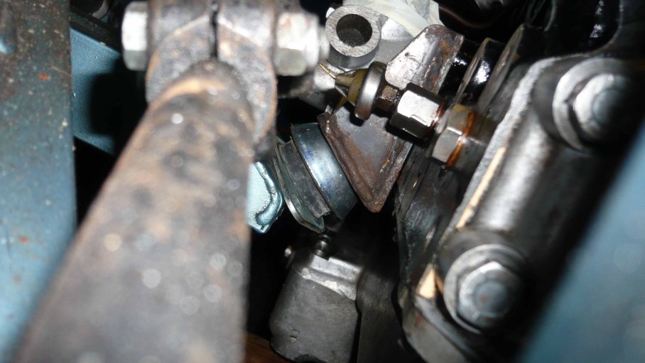
On reflection the only way to change the fan belt was to take the water pump off. What must go on in the mind of a man who thinks that is a good idea? A solution was needed.

It turns out a bespoke solution was needed as the Alternator mounting was also non-standard and an integrated solution would be required.

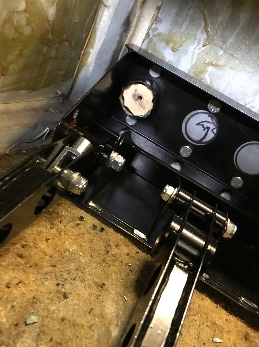
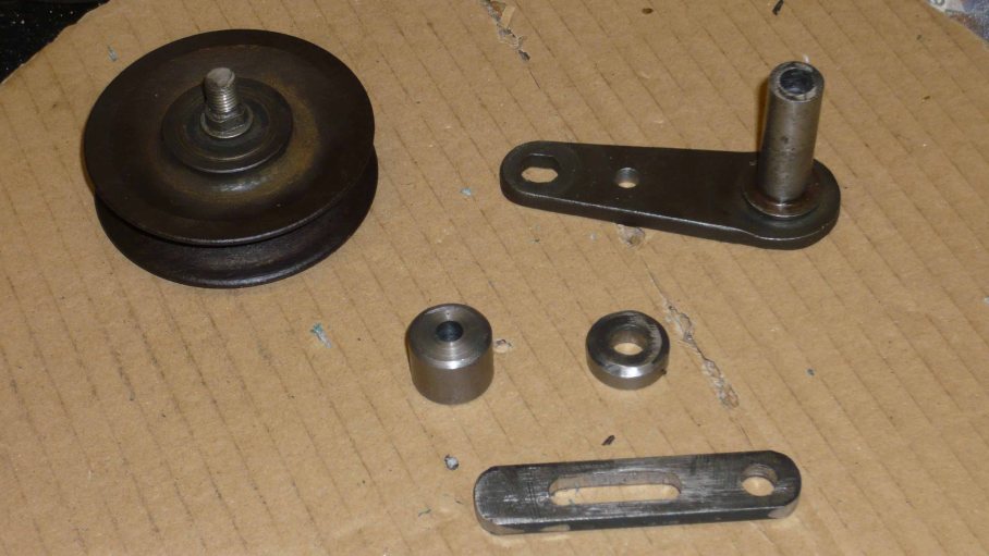
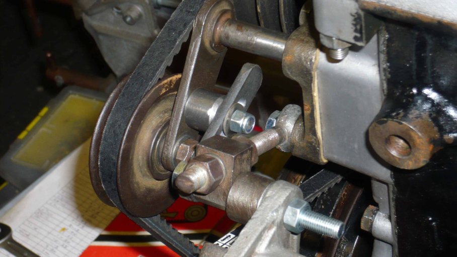
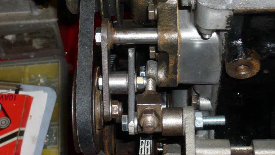
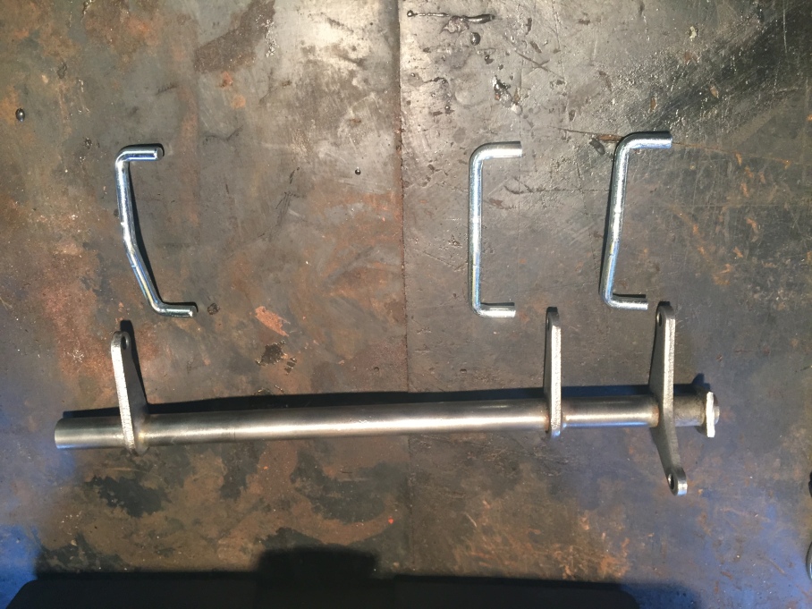
Jerry located a jockey wheel and went about designing a system by which both the alternator belt and the fan belt could be adjusted within the small amount of space that existed.

What he came up with is a work of art, feast your eyes on this ladies and gentlemen….

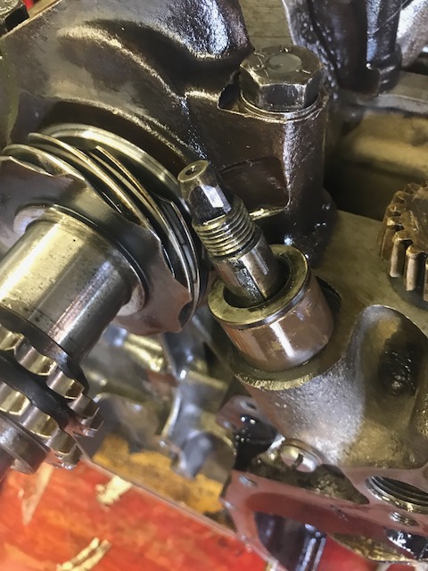
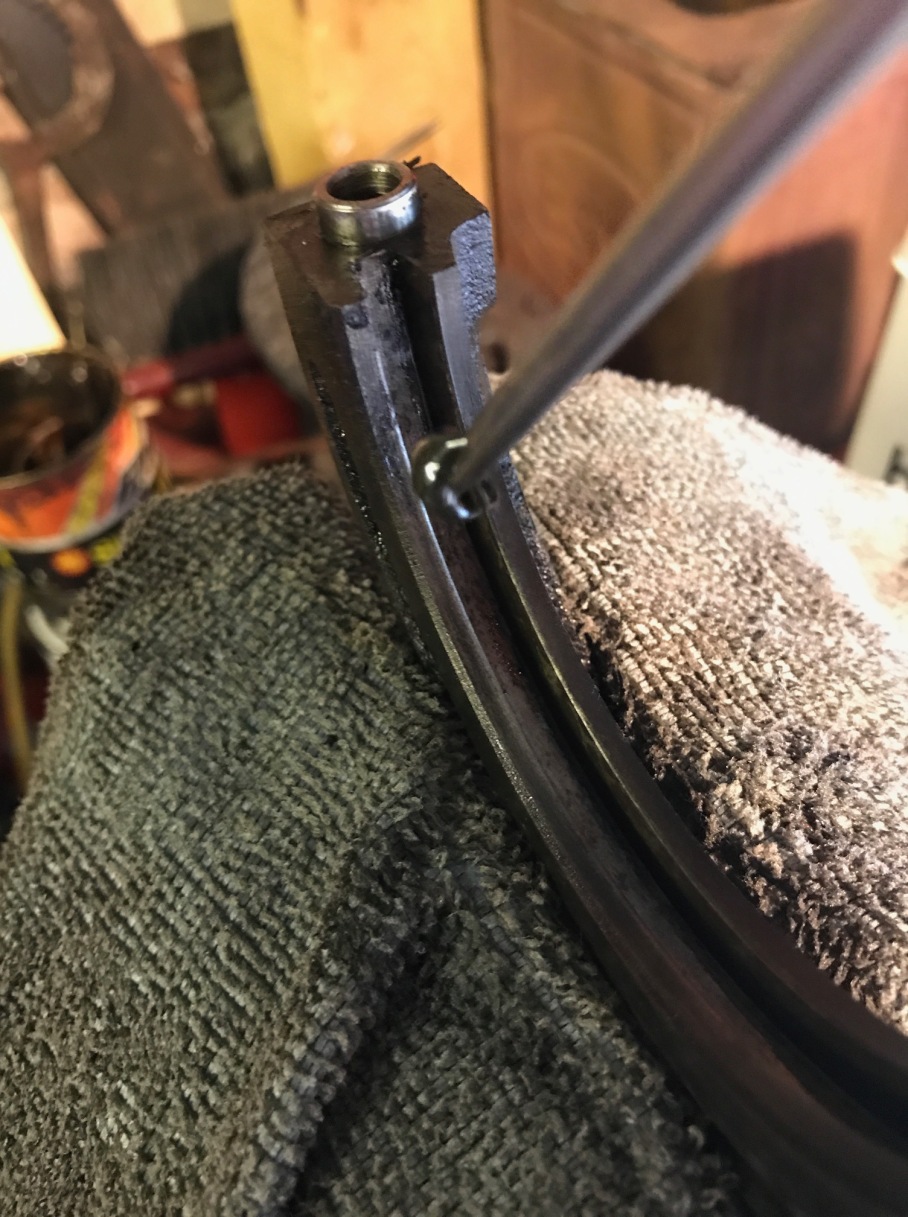
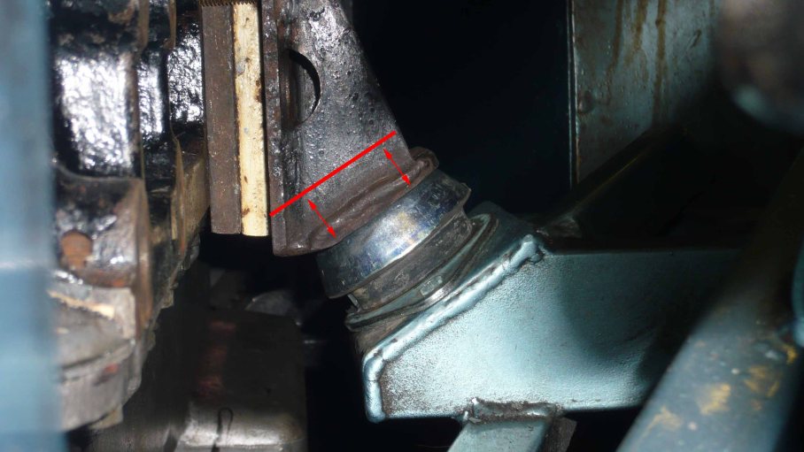
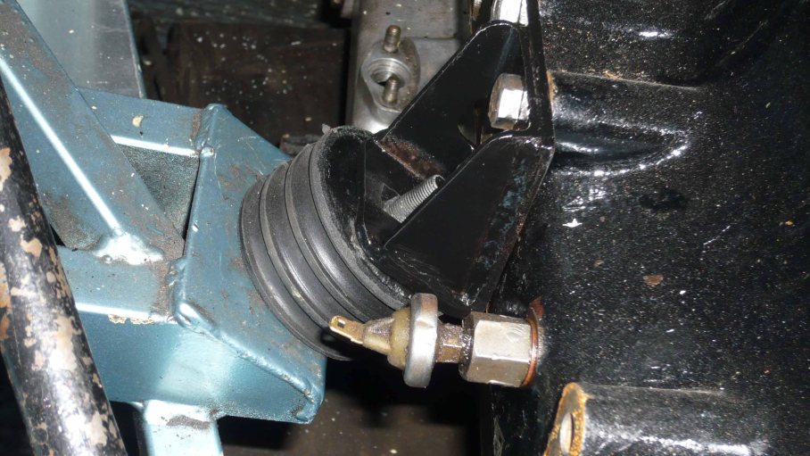
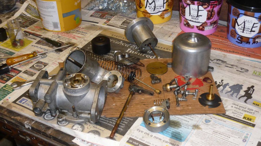
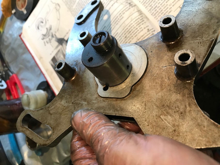
The Jockey wheel was stripped down and the shaft cut

P1040909a

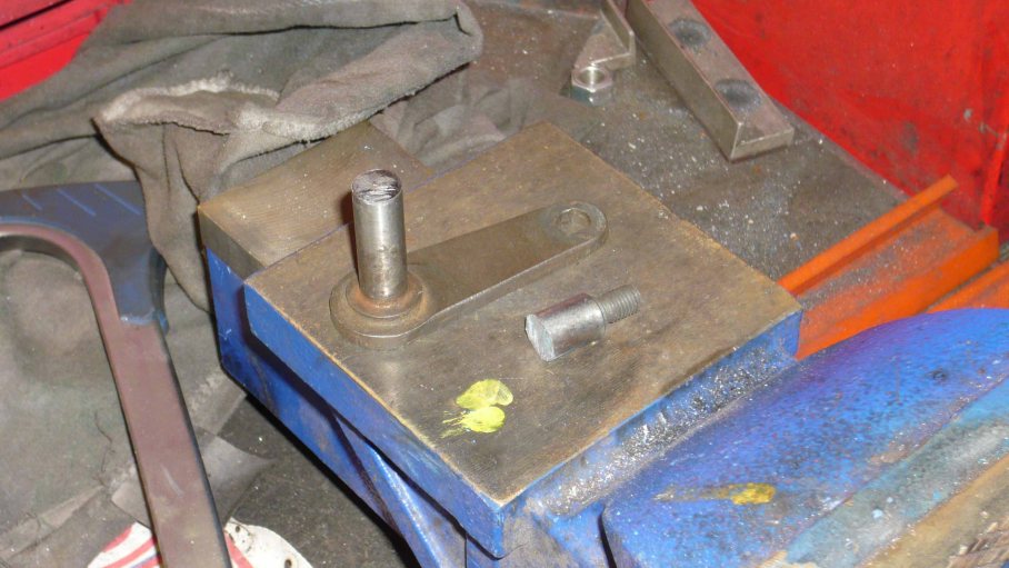
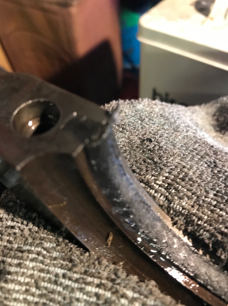
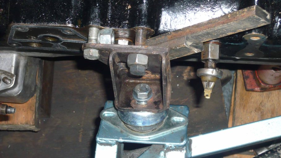
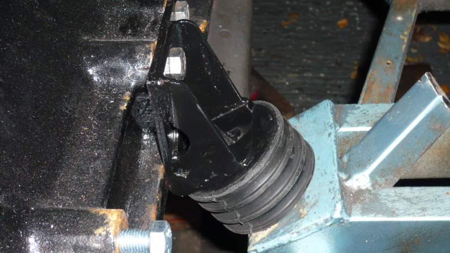
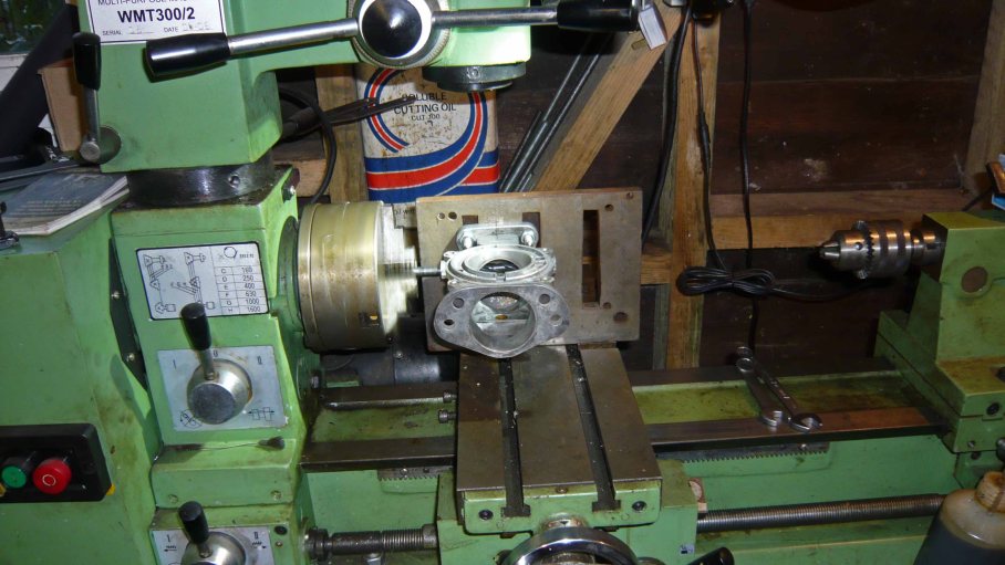
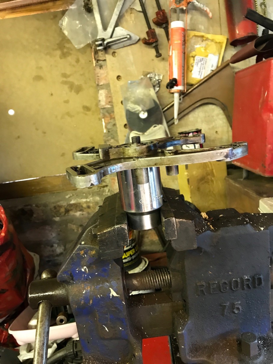
The jockey wheel shaft was drilled out to accept a bolt (to one of the water pump mounting points). A new slotted bracket was manufactured that would anchor on the alternator mounting bracket. A couple of spacers where also turned to get everything in the right position.

P1040910a

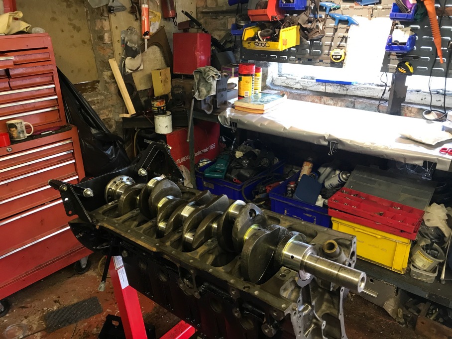
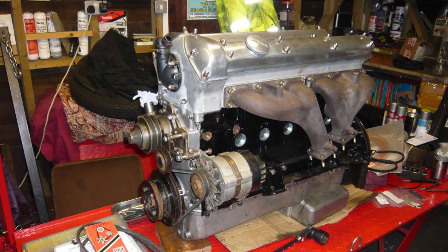
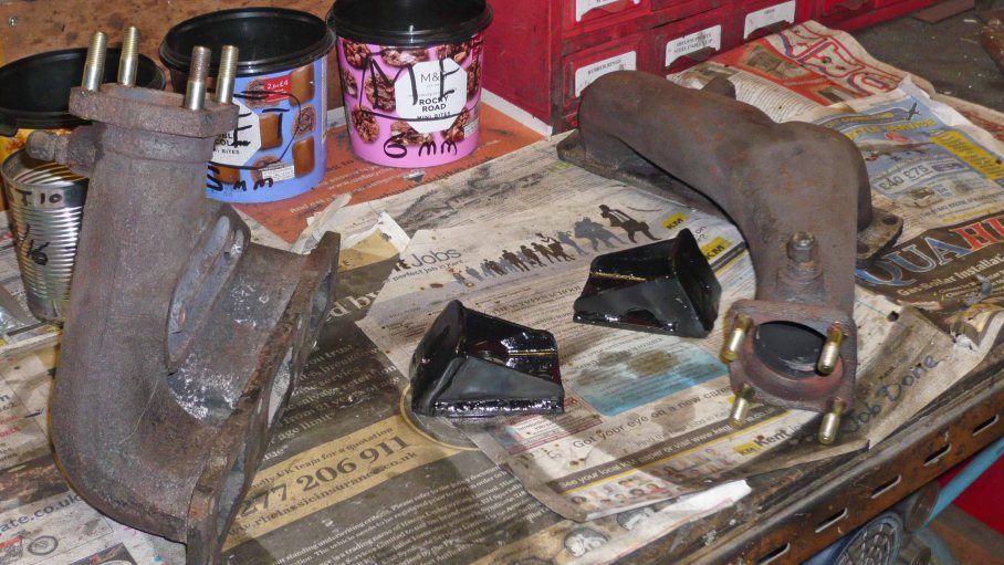
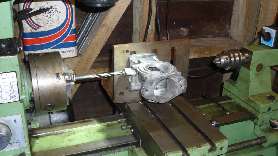
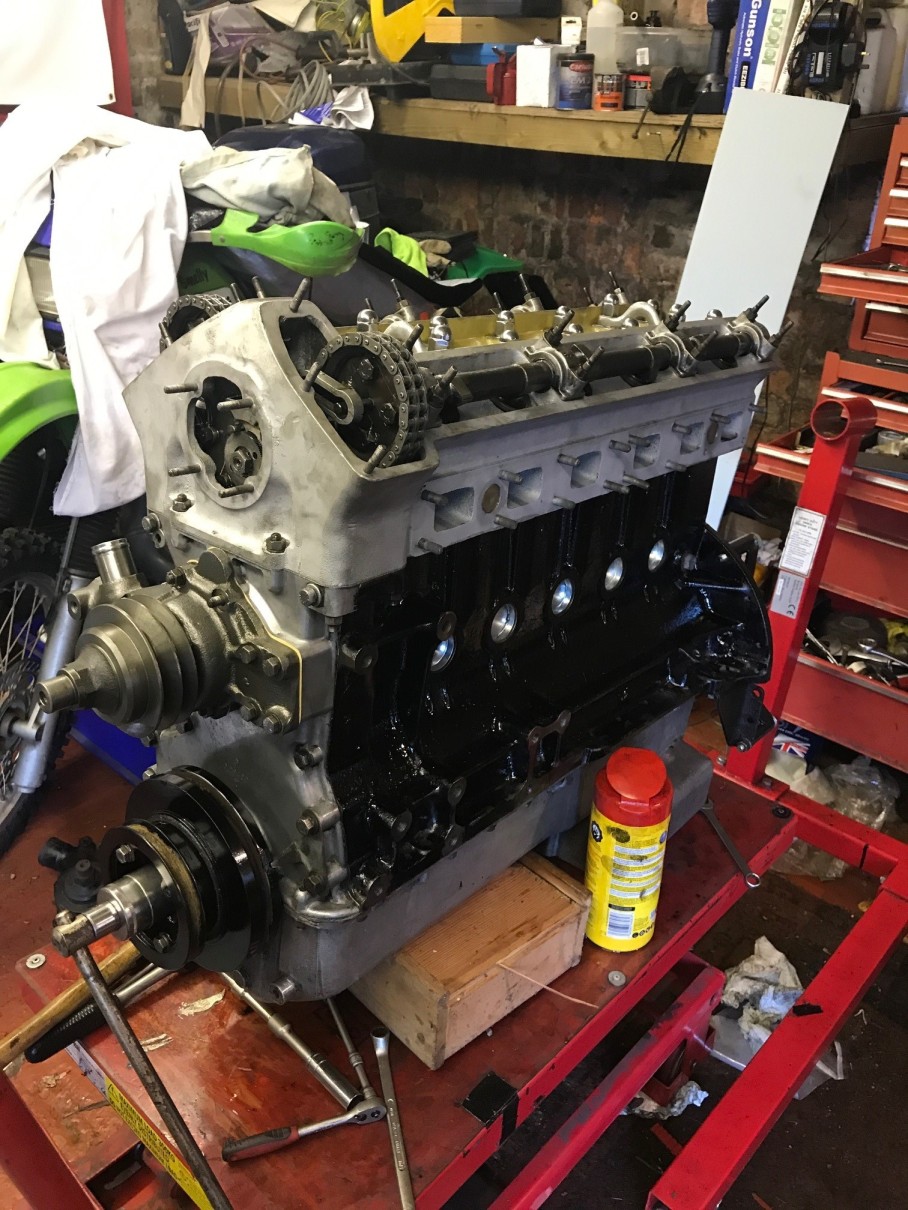
I trial fit to get the spacing right… This picture also shows the newly re-studed exhaust manifolds complete with new brass nuts. There is something about a set of brass nuts, they just look so right…

Challenger E type engine s1

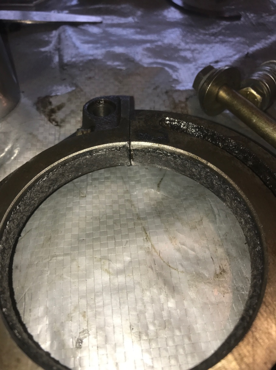
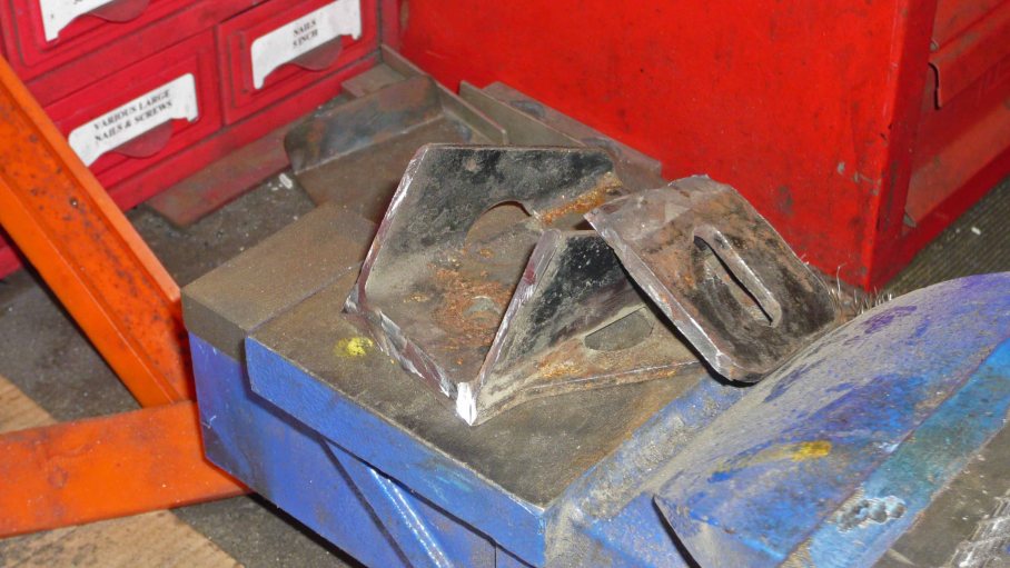
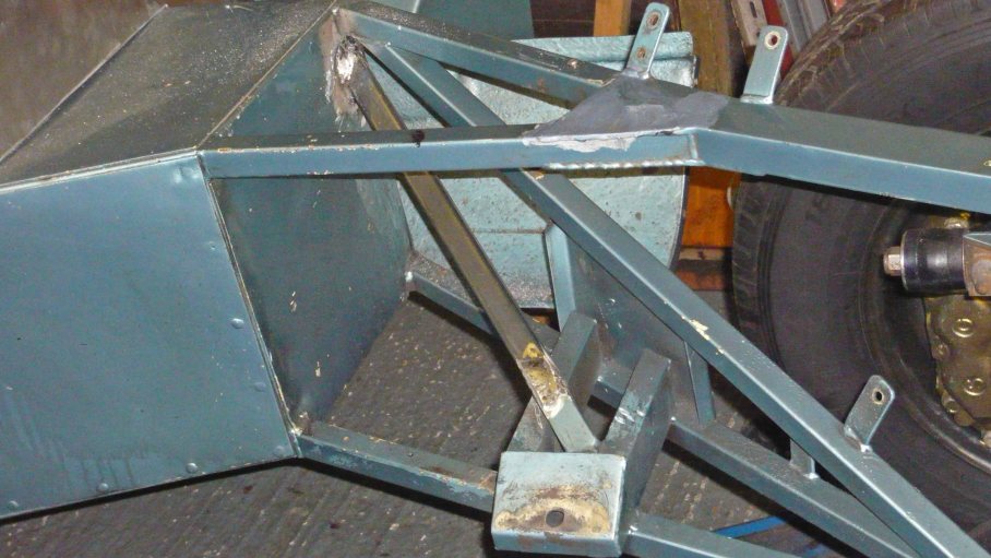
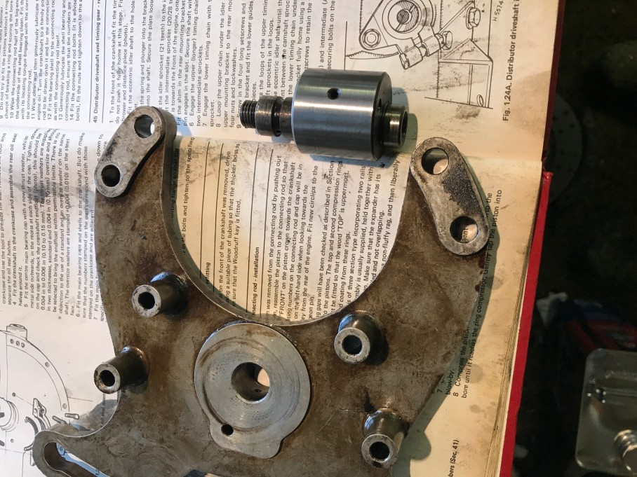
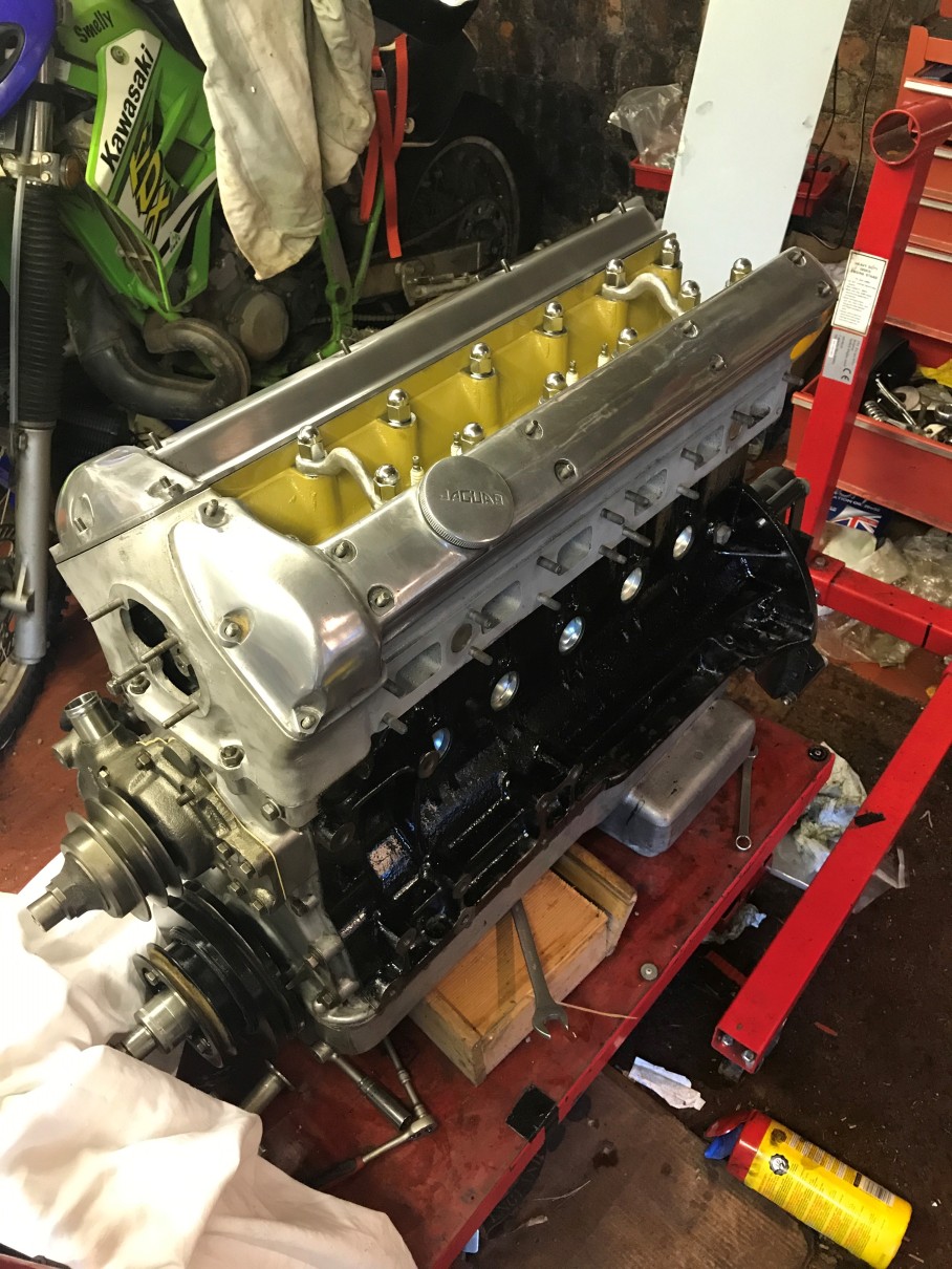
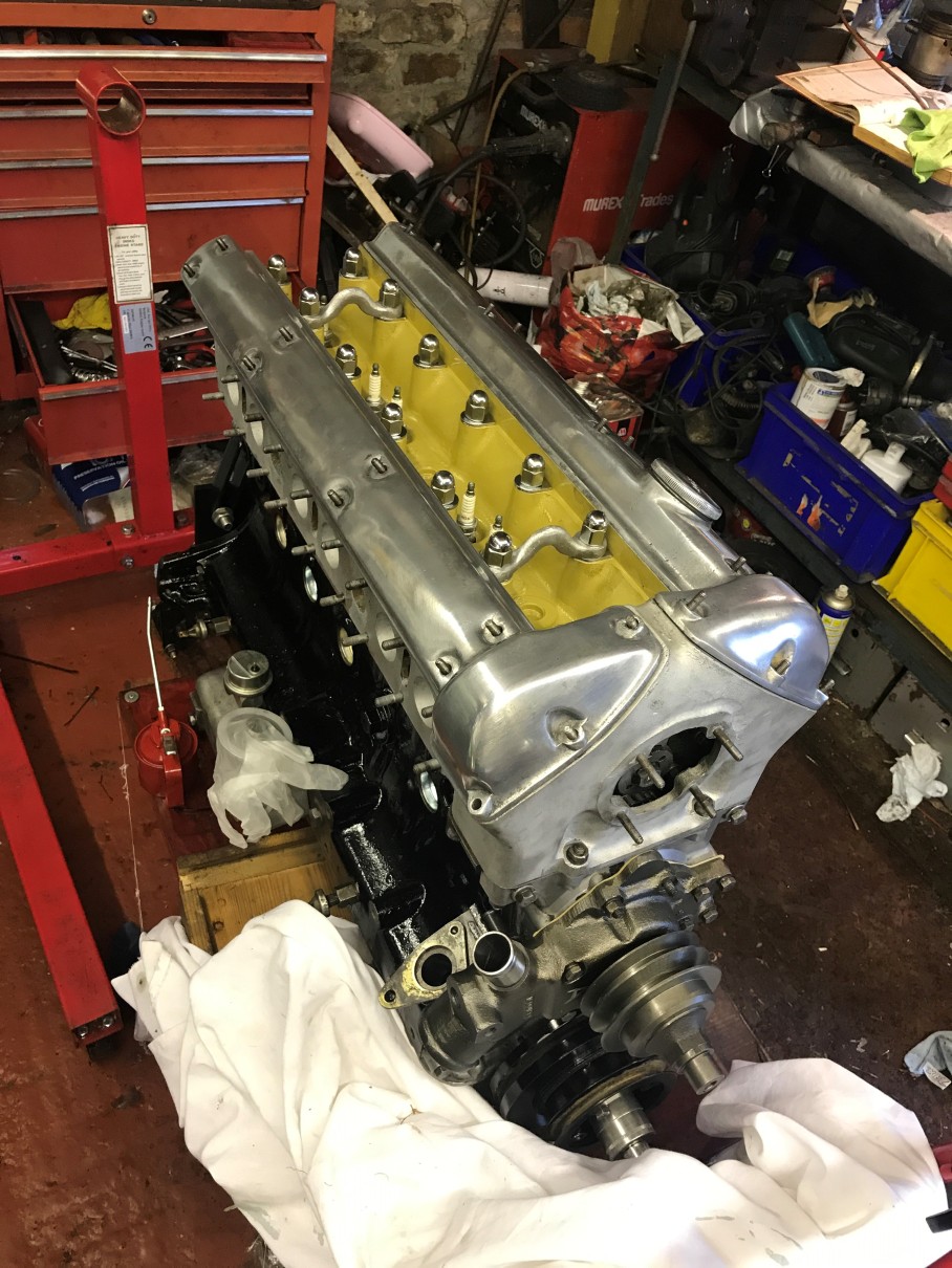
Then, in a magical form of wizardry, all the parts came together to do this…

P1040912a

More of the pictures….

P1040913a

P1040911a

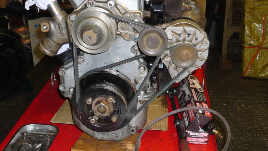
I find this deeply impressive…. Its also such a shame that once installed this will be almost invisible. However, if you are ever fortunate enough to be run over by Lady Marilyn, please take a good look as it passes over you.

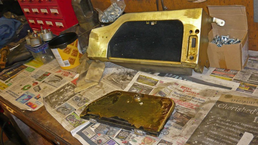
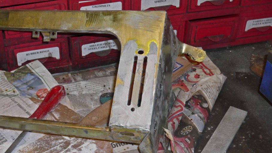
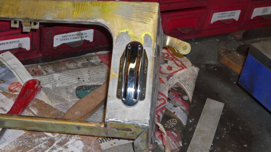
Around the same time work was ongoing to turn the series 2 glove box into a series one item. I don’t know why a series two part came to be on the car, but it did and it wasn’t right. The S1 heater controls are just lovely pieces of kit, that have a real period feel and lots of chrome. I’d already fitted the S1 choke control to the dashboard, Jerry set about modifying the glove box to suit.

Off came the leather cloth to reveal the metalwork…

P1040884a

The S2 switch gear is recessed (its like a pull out lever afair, so this was cut out.

P1040899a

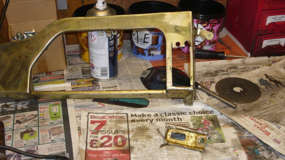
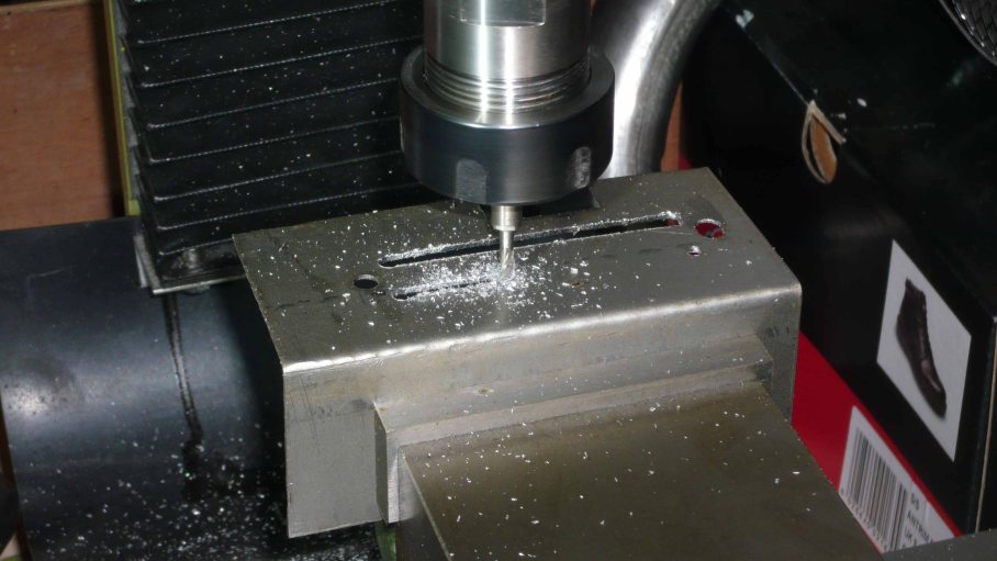
A replacement panel was cut and the lever slots milled into it.

P1040901a

This was tacked into place and a skim of filler applied to true the new surface

P1040905a

P1040907a

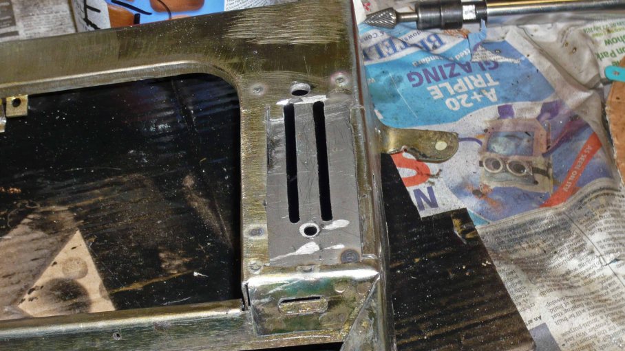
All ready to receive the newly acquired brightwork.

e type s1 heater controls

The glove box will now be trimmed in new leather cloth to match the Dashboard.

That onlt leaves the centre panel. This had been butchered to fit a modern day hazard switch. Once the panel was stripped down, the result want pretty.

P1040800

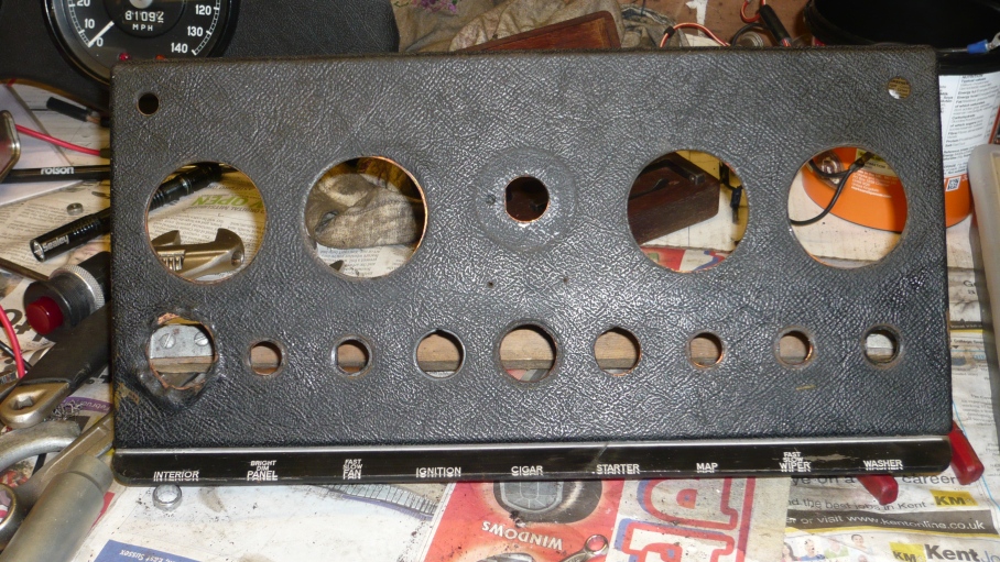
Note the butchered hole on the far left. This could have been repaired but as the panel needed work and I particularly like the early E center panel, like this one…

DSC_0813a

Jerry knew someone with the right material and a waterjet company that could cut the part. No brainer, lets get on and do it.

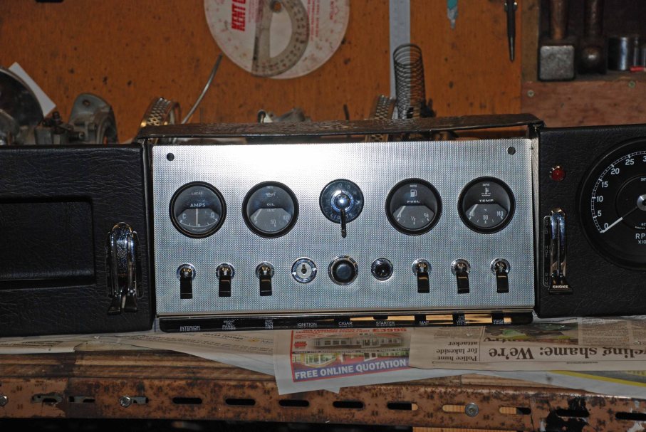
Ah, but if I’m going for a new panel then really I should do something about the gauges…

So I got a set of refurb kits and set about reconditioning a full set of the correct gauges…

gauges

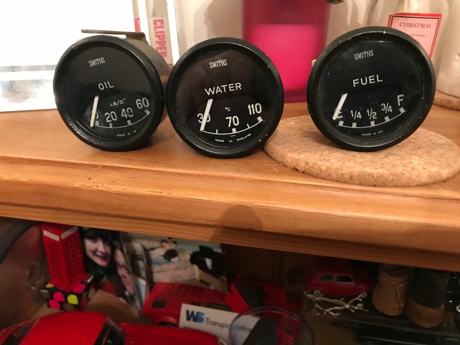
The oil pressure face has deteriorated, so I have a new one and will post pictures of the refurbed gauges when installed into the new panel.

The progress continues at a great rate of knots….


A not insurmountable problem

First Job at Jerry’s was to mount the radiator. This is a cracking piece of kit, custom made to my design in China. Now O know what you’re expecting from anything made in China, but I’ve received it and it’s spot on. It was made in less than a week and in my garage two weeks later all for less than the re-core costs of the original radiator – just £300 all in.

E type alloy radiator

Challenger e-type radiator

Check them out and take my recommendation that the product is excellent.

winner_racing_spares

The first job was to mount the new rad, ensure it cleared the bonnet (to out American readers thats the thing that covers the bit with the engine in) Once the correct angle had been established make a couple of mounting brackets and remove for real fitment at a later date.

There will be twin electric fans and a thermostatic controller fitted. These old girls can run hot and I want to be sure the cooling system is up to that one sunny day we get every year…

Next the Engine went in, well when I say went in, was positioned correctly se Jerry could work out what to do with the engine mountings. The car had come with early mountings, but both were broken when I picked her up. I’d got new ones but had never fitted them.

Jerry positioned the engine and checked for lots of known problems. Too low and the carbs catch the steering column, too high and they catch the bonnet. Like the Goldilocks, it had to be just right.

P1040817a (2)

The early mountings, didn’t actually fit. Using the brackets and mountings per how the car was received put masses of stress onto the joints themselves, which is probably why they disintegrated in the first place.

Mounting 1

To try and get them to align a number of spacers were tried…. But it was becoming unmanageable and the angles still were not right.

Mounting 3

Mounting 2

So, the Jerry-Meister cut up the bracket and remade it to suit the more robust later XJ6 mountings. What we ended up with as another work of art that fits properly and maintains the correct position of the engine in the chassis.

P1040871a

Brackets modified and standard mountings used, all is well. The mounting stud is mid hole and the engine – and more importantly Carbs – are at the right height.

P1040879a

NS and OS brackets and mountings in all their glory.

P1040878a

In the picture above you can see a chassis member which has been cut. This was done by the previous owner in order to place the battery at the front of the passenger foot well. This is butchery in my book and this will be properly replaced with new steel and the batter relocated to the correct position at the front of the engine.

e type shassis repair

Above the chassis rail is magically back in place….

Below the modified and repainted engine mountings.

P1040872a

Also pictured above are the re-studded exhaust manifolds. The old studs were removed and although one stud was missing the thread was sound enough to stand a re-cut and the new studs inserted. – proper job.


Suckers….

When lady Marilyn first rolled off the trailer 3 years ago, and I do mean rolled as the bugger wouldn’t start, the first problem came to light. When I say the first problem, that’s like the first grain of a sand storm.

The reason she wouldn’t start is that the Carbs were buggered. They were full of crud, the diaphragms were all shagged, the floats were all punctured and the AED didn’t work.

Its only the carbs I thought, we’ll be done in a jiffy.

HD8 float bowl

So I cleaned them all up, bought new diaphragm and jet kits and new floats. I then rebuilt them


Heres the thing. I was so focussed on getting them in decent order, and they were in such bad condition that I only fixed what I saw. The engine ran fine when they’d been re installed but I didn’t set them up properly as the engine needed stripping anyway.

Once Obi-Wan Preston-Ladd got his hands on them he diagnosed an Issue that I hadn’t spotted. The butterfly shaft on number one carb had worn the carb body and needed some work.  This was because the existing throttle linkage had been attached to the butterfly spindle on carb number one and the other end of the spindle connected to the throttle shaft that moved the other two carbs.

IMG_4151

Above you can see the throttle linkage to the first carb, the other end of the spindle is fastened to the linkage arm which sits under the manifold and operates the other two carbs.

IMG_4127

There are a couple of problems with this. slack in the linkage (and there must be some, its a moving part) means that the second two carbs are fractionally behind the first in terms of operation as this first is hard connected to the throttle cable. This is not a good idea and an alternative throttle control system will be designed and made later, firstly though carb one needed repairing. Fixing the problem involved boring the carb body and fitting new bushes to take the slack out.

P1040864a

P1040862a

P1040861a

This was one of the times I realised how lucky I was to have Jerry finish the car for me.

Once the new bushes were in carb number one (closest to the bulkhead) carb 2 was also resealed and carb three was fine – except Jerry found one of the butterfly screws loose. That could have been a problem….

P1040841a

They are all done now and to prevent the same thing happening again, Jerry is making a new linkage to prevent premature wear in the future.

While we’re on this picture, Jerry also made a splash guard yo protect the master cylinders for the new pedal box as well as a new foot well cover. In addition the fluid reservoirs were mounted an a newly manufactured bracket and fixed to the equally new trim panels (shown in the picture behind the reservoirs).

There’s a new trim panel on each side that Jerry has made from ali sheet.

P1040848a


In the picture above the feed lines have been fitted too.


A Merry Jerry Christmas

Those that visit here often will know how painfully slow this project is progressing…. I am acutely aware and frequently reminded that its 3 years since The E Type rolled off the trailer, and refused to start, for the first time.

Something needed to be done, and I wasn’t doing it nearly fast enough. I needed a hero to step in. All the way through the build I’ve had constant support and encouragement from the Club Technical Officer, Jerry Preston-Ladd. Jerry has built or substantially improved a number of Challengers and his knowledge and skill are beyond compare in the real world. He’s also rebuilding a steam locomotive, which is no mean feat. If your a lover of this blog, throw a few quid their way as its an expensive old process.

4253 Locomotive

So I called Jerry and asked if he had a slot on his waiting list I could slide Lady Marilyn into. As luck would have it he’d just finished a lovely Challenger and he was only waiting for its owner to collect it.

Piece of cake, I’ll trailer my car down and deliver the other one to its owner.

so, the plans were laid. I’d collect all the bits and bobs together, set off on an expedition to the mysterious land of “The South” and I could once again begin to dream of having a completed car.

All the updates that will follow this point are Jerry’s work, with some help from Gary (a fellow enthusiast) where more hands are required.

Prepare to Marvel at the work that goes into the car now and the rate of progress that outstrips anything I could have dreamed of.

So, Here she is ready for her trip to Chez Jerry

way down

and once down there was the small matter of delivering Roys car, which really is a cracker, but I didnt take a cracking picture of it…

Mikes

As soon as I got home the updates started flowing….. Read on.


Clutching at Straws….

You have no idea how hard it is to find a clutch kit for a series 1 or 2 XJ6… There are some specialists who’ll relieve you of many hundreds of pounds for one because it fits an E Type, therefore you must have one and ergo you have more money than sense. I have more sense than money and my sense is rapidly becoming incensed.

Twice I’ve hit the buy it now button from the well known retched hive of  villainy, otherwise known as E-bay. Twice I’ve been told “we don’t do them any more” so take the twatting listing down you moron – I thought.

Finally I came across a listing claiming to have the very part in stock, and cheaper than the others too. Northern Components were the vendor, I clicked the link, paid (again) and sat back for the “we’re sorry we don’t have that part in stock” email. But No, the next email was a dispatch notification, followed by a txt advising when the driver would be here and shortly after a new clutch kit was in my office. Thats office, not orifice, which, incidentally is where I was going to shove the ebay’ers non existent listings.

E Type Clutch kit

Genuine parts, and a snip of a price. Rear water jacket cover fitted…

XKE engine rear

Next job was to replace the flywheel, this had previously been skimmed and balanced by W Drake in Bradford. New locking plate, of course, just the six bolts and ta-dar…

E-TYpe flywheel

The Pressure plate locating holes needed opining out a little to accept the three flywheel dowels, just a paint thickness, and it all bolted up nicely. I kept the pressure plate finger tight so I could still move the friction plate as the alignment is tricky. The friction plate to gearbox clearance is bugger all of nothing and I needed to ensure adjustment.

E Type clutch

E-Type clutch

I also did the last few minor jobs and we’ll call the engine complete as it need to be at this stage. I’m using new mountings and this will need adjustment, hence the manifolds are going to stay off until after the rewire (which is the next major job).

For now I just want to take a minute to compare where we came from….


Rebuilding the engine has been a journey interspaced with long periods of inactivity. Meanwhile the end is in sight and once the wiring is done – along with new brake lines – the engine and box can go back in and after a few smallish jobs are tackled, I’ll finally be driving the old girl!

Can’t wait…..

Heading for Victory

XJ6 cam chain

Whats missing from this picture? well,  the rest of the engine, obviously, but specifically I should have added the cam speckets at this point, more of this later… The other thing I didnt do is check that the upper chain tensioner moved smoothly. I didnt and, once assembled, it didn’t.

So back off it came and sure enough the bugger wouldn’t budge.

e type cam chain tensioner

Time for some light persuasion… With the aid of a deep socket I tapped the tensioner free

xk cam chain

It didn’t take much and there wasn’t any real pick up, it was just held in with crud

XJ6 cam chain tensioner

Once cleaned up it was all re-assembled and then it was time to add the timing cover, which was easy enough. I borrowed Jerry’s technique of seating the crank oil seal in the timing cover and sliding it along the crank. Worked well and didn’t damage the seal.

The sump came next and, again, all very straight forward.

Now to add the new head bolts. I unpacked the parts sent by David Manners many moons ago. I’d gone for the 4 long studs pack as I like the look of the lifting lugs. I would use them to actually lift the lump, but they look nice….

Here’s the set unpacked…

XK xj6 head studs

I have three long studs to match the 4 mounting holes. Something has gone awry…

So, armed with my best argumentative voice I called David Manners to tell them the parts they supplied… cough… two years ago were, in fact, wrong.

Called the help line, gave them my postcode, waited…

Sorry sir cant find the order, oh, it wasn’t 2015 was it?

Well, yes, as a matter of fact it was. Can’t rush an engine build….

No problem, what do you need?

Well, just another long stud…

No problem, I’ll get it in the post tonight.

Next day it turned up, express courier, FOC. Now thats what I cann customer service, if you need parts for your Jag, go there first. Top company….

david manners

So, equipped with the new studs, re-assembly can continue….

Oh, there’s a new water pump in there too, that came to DMG as well, as did the new core plugs.

Now time to drop the head on. Freshly painted in the correct Harvest Gold, specially mixed by HMG paints, and add the new head nuts and lifting lugs.

E type engine

This picture shows the cam sprockets fitted. This wasn’t actually as easy as you might think. Early on in this post I advised that I’d forgotten to fit these before the head. I found out to my cost that there’s no way they’ll fit with the cams in place, to time to pull them out again. Its not actually the worst idea, the head was built up over a year ago, so pulling the cams allowed me add new oil to the bearings and fill the camshaft oilway at the same time. Once the cams are out the sprockets need to be pulled apart. Remove the circlip and pull the inner sprocket from the splined on outer (should have photographed this as its a work of art) slide the inner home and then – like a Chinese puzzle, feel the sprocket outer into the chain.

Re-installing the cams needs a little jig to hold the cam in the right position whilst the journal caps are torqued down. Without it there is no way to hold the cam as it pushed just one valve almost fully down and therefore, the force of the spring spins the crank.

With the cams torqued back down align the sprocket mounting holes, noting that they are off set on purpose, and then re-engage the splines before replacing the circlip and tightening the bolts… It can be done – but I wouldn’t call it easy…

Once that’s done, there’s just a few bits and bobs to add, such as the flywheel, beforerI can call the block built.

It is a work of art though. Modern engines could never look as pretty…

built 2

Built

I think I’m just one blog post from closing the Engine chapter, happy days!

The (woodruff) Key to Success

As I was finishing up my last stint in the garage, I realised I’d lost my first part. Despite a pathological need to bag every single piece in zip lock bags with sharpie written descriptions I’d lost a bit. Bugger.

The bit is question was only a woodruff  key from the end of the crank (the other two identical keys had made it into and out of the bag). Could be worse, I’ll just get onto SC parts and order a replacement. So I did. Then things took a turn for the worse. Read on….

The reason I like SC Parts is they lay the site out like the Jaguar parts manual, making it easy to find stuff. Here’s the page…

xj6 woodruff kek

The fella I need is part 88…

woodruff key - e type

Now SC parts are a bit pricey and yes £4.33 seemed a bit steep, but time is valuable too (check out the we buy any car advert, now with added desperation) So I added it to the basket and checked out…

Right about then Dick Turpin came riding on to my PC. It wasn’t so much “stand and deliver” as “how much to deliver?”

SC Parts 
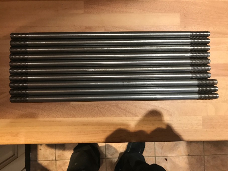
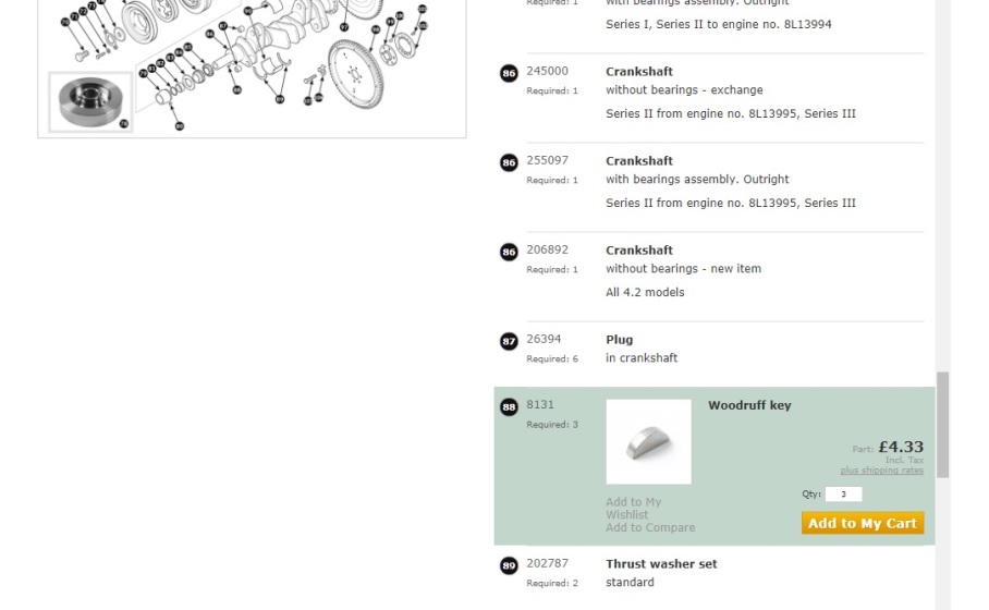
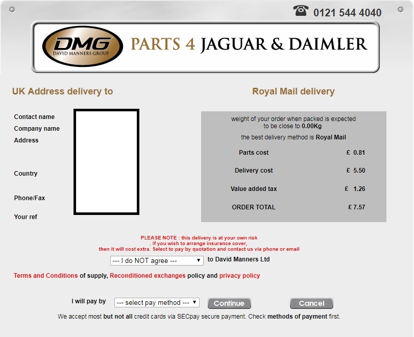
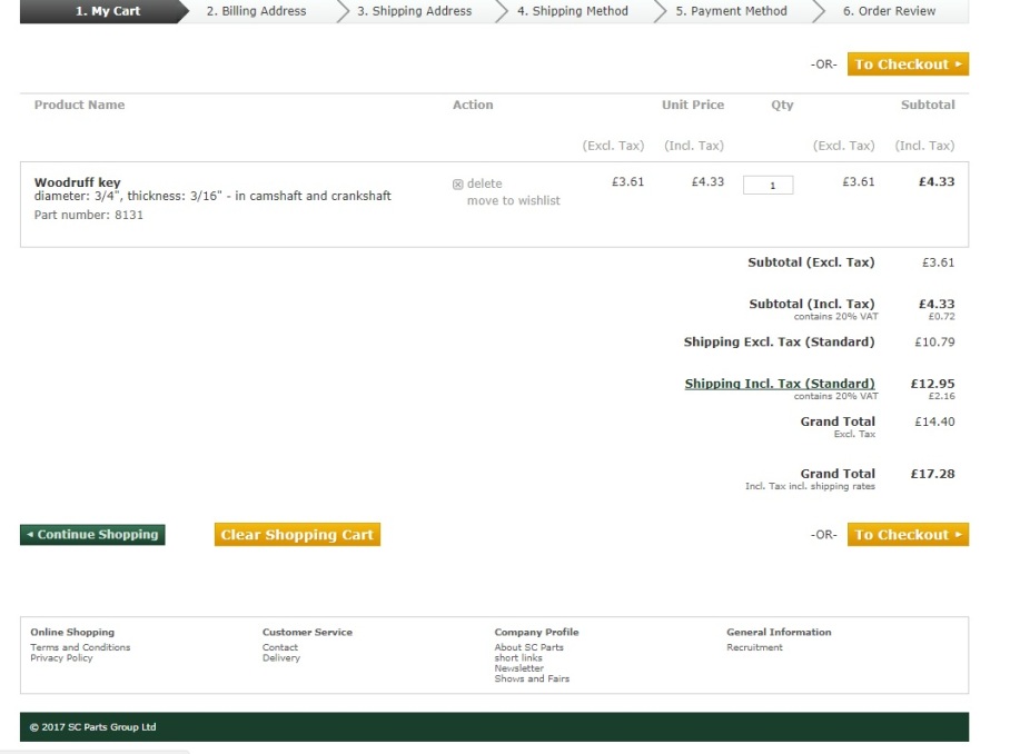
£12.95?? for a sodding woodruff key? It’d be cheaper to send a taxi for it. Must be a mistake, said my misguided faith in human nature, I’ll give them a call. So I did.

Nice chap answers the phone, I tell him what it says on the screen and he says,

“yep, that’s right. We only have couriers”

Cant you use royal mail?

“Err it’s policy to use a courier, but” said the man positive he could turn round the situation with a special offer, “you could by loads more stuff and it wouldn’t cost any more.”

“Really, so anything else I want I get for free?” (smartarse mode is firmly engaged at this point.

“Er, no, but the postage wouldn’t cost any more.”

“But I don’t need anything else, otherwise, (you thick twat – I thought), I would have bought it”

“Ah”, said the man, drawing on his never fail, reserve argument, “you could buy a couple of gallons of oil, it will always come in handy”

“Listen pal, if I had any more oil I’d have to join OPEC”

“In that case, ‘Sir’ (sir being an anagram for ‘bastard customer’ – some letters need to be added, obviously) I can’t help you”

Finally, some kind of sense.

Back to my Jaguar parts book, google the part number, stocked by David Manners, a far more reasonable 81p  and £5.50 to deliver, total, with vat, £7.57 almost a tenner less than SC Parts or 56% less if you like percentages.

David Manners

It arrived, two days later, by post…

Well done David manners I’ll start with you in future.

Rebuilding old cars can be a bloody mine field and an expensive one at that. It really does pay to shop around, even at the bottom end of the price bracket.

Bet I lose the bugger before it gets fitted…..


The Big Build….

After the trauma of the first attempt, the block and main caps had been line bored, time to see how much of a difference that made. The call came mid week “your block is ready” which translates roughly to “you bank account will soon be empty”. Still, full of the reckless abandonment of hope, I sent off in the company van to recover said block, I drop off my worldly net worth at the same time.

The chap at Drakes has build the crank into the block to check the results of the line boring, but stressed to me that it needed stripping back down again and cleaning thoroughly before re-assembly…

So I did as I was advised and for the second time went about cleaning the block and all the oil ways, I had previously invested in a borescope which comes in handy for checking the main oil way.

All was good and using the 12 bore shot gun brush I’d bought previously cleaning the last remnants of remaining swarf was a doddle.

That done, time to replace my feeble first attempt at the rope seal, any more problems with the rope and I think I’d be hanging from one… This time all went to plan and it seemed like I’d done a half decent job. I checked the two haves whilst the crank was out and they were tight but moving – not dissimilar to me on a night out.

Main shells back in, upper rope seal mounted, and crank laid back in. Center main in place and end float was good. So torqued all the caps up and, thank the lord, we still had movement.

Jaguar crank assembly

Pistons next, lets just take a minute to savor the lovely box of Mahle goodies.

Mahle pistons

All the old circlips and gudgeon pins came out easily, and the new ones slipped on equally easily. Word of caution, circlips were originally invented as a Japanese fighting weapon. They have been know to take the eyes out of invading enemies before vanishing from the face of the earth. Beware and treat them with the reverence they deserve.

Before inserting the pistons check the rings, they came from the factory with the ring gaps all lined up. Not good, the gaps should be spaced apart to avoid blow through. I always avoid blow through, it can be painful at times….

Jaguar piston rings

Rings positioned cirrectly and with a squirt of oil it was time for the ring compressor.

Oiling the bores thoroughly before insertion and making sure the pistons all pointed to the front as they should, tapping each piston home with a hammer shaft – feeling for the click as they slip home and making sure a ring didn’t pop out of the clamp. All this while first making sure that the con rods were all on the right journal and facing the right way. Job done.

All done and still turning freely.

I sat the engine up again before inserting the distributer/oil pump drive. Positioning is a rough process as the timing will be set later and it just a case of getting the off set slot in the distributer roughly in the right place at TDC.

Jag oil pump

Another simple task crossed off.

Next was to put the partially assembled block on to the engine stand and assemble the cam chains.

The upper cam chain is like an origami puzzle, specifically the chain catcher bit.

but what’s a few fingers between friends?

Its the puzzle of getting the bolt through the cain catcher and the casting, into the spacer (which you have to hold with long nose pliers because your fingers wont reach) through the chain guide and into the block. Sounds easy doesnt it?? I’ve decided the Jaguar engine line was staffed by these guys…

pans-labyrinth

That was it for that day, except to say I’ve found my first missing part from the strip down, its only a woodruff key and should be easy enough to replace. Until next time….

thats all folks


At braking point….

given the debarcle with the crankshaft, I used the rest of the day to fit the   OBP pedal box. Its a nice piece of kit but as the master cylinders are the other side of the bulkhead 38mm holes have to be drilled and there not much clearance between the master cylinder body hole and the mounting points..

IMG_7851

You can see the problem in the above picture. My drilling is about as accurate as a Jeremy Corbyn manifesto, so I needed and ingenious solution.

Its easy to line the pedal box up and drill the mountings, using and 8.5mm bit to mark the centre and then pilot drill before going full size. I did thin and bolted the box in place.

Next I’ll need a hole saw, as opposed to a sore hole (I miss  Janet and John )

Next came a rare flash of inspiration which might be of use to others, so here goes. The hole diameter required is 38mm, so with a 38 mm hole saw I drilled a pick of 25mm timber.

IMG_7852

I carefully prised the slug out of the hole saw. The slug is smaller than 38mm so I wrapped gaffer tape around it until it was back to the correct size

IMG_7853

I then used it as a guide to mark the centre of the master cylinder hole.

IMG_7854

Pilot grill through the centre, and hey presto…

IMG_7855

Next the fairly simple job of adding the master cylinders, set to 50/50 for the brakes front to rear.

The brakes will be treated to all new lines, but that’s a job for another day.

Rage against the Machine (shop)

Engine rebuild day dawned, finally all the little bits in the garage would become one big bit, or at least that was the plan.

Block mounted on the engine stand, old shells in place, crank positioned

IMG_7834

So, time to attack the dreaded….

e type rope seal

The rope seals had been soaking in premium engine oil for two days….

IMG_7837

The two seal holders were clean, and we were ready for the off. I added an inch of gasket sealer to the leading edge of the holder (when viewed from the rear the crank spins anticlockwise)

IMG_7839

Then it was time for the dreaded rolling, I used a hammer shaft and starting at the centre worked the seal into the slot moving outwards. This took about 20 minutes and all looked good.

I used a stanley blade to shave off the excess and then clamped it to the crank.

IMG_7844

BUGGER, it way just too tight. I took the two halves apart and then lightly hammered the hammer shaft I’d used to roll the seal into place. One half did give a little, clamped them back up and the fit was fine, tight but could be rotated by hand. Problem was that extra bit of give left me with a 3mm gap.

IMG_7848

Double bugger and a new set of seals required.

Oh well, on with the setting of the crank on the mains.

IMG_7845

Lovely new shells in place. Lowered the crank into position and added the centre main cap (as this has the thrust bearings in and I wanted to check end float). As soon as I got beyond finger tight on the bolts the crank locked up. I needed a breaker bar to shift it – not good.

I spent the next two hours faffing around shells out and cleaned, old thrusts tried, the remaining bearing caps fitted loosely, every time the crank locked up.

Something isnt right.

The crank mic’d up as 20 tho under standard (as it should, having been ground) the shells mic at 10 tho each over the originals (matches the crank) maybe the mains have been ground a little eccentric. That I cant check though. So, strip it all down again, pack up in the Landy and back to the machine shop so they can figure out whats wrong.

The crank was as free as a bird, pre regrind, something much have happened during the grinding. I’ll report back when they’ve done the investigation and can shed some light on the problem….

Meanwhile, its back to the brakes, oh and order some more….

e type rope seal

🙂